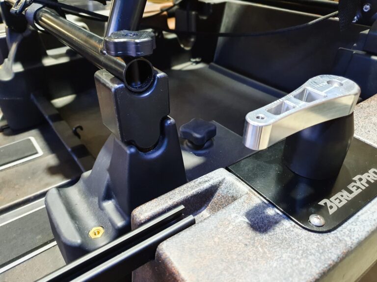
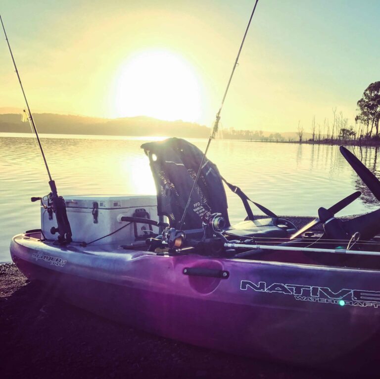
This is how to install the BerleyPro Tacklepod Battery and Transducer kit on a Viking Tacklepod. The benefits of this are to move the batteries and wiring to the back of the pod and out of your way. This frees up usable space and keeps your wiring and batteries away from wet and potentially damaging items.
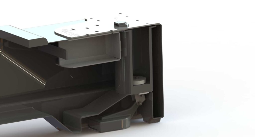
The BerleyPro kit contains two aluminium trays for the batteries to sit in and a laser cut aluminium cover plate on the top as shown. The transducer mount uses a plastic plug and stainless steel mounting plate to allow quick install of a variety of sounders using the mounting plates provided.
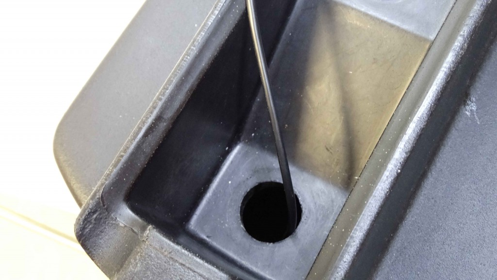
The first thing we do to install the kit is to mount the transducer. First we need to pull the transducer cable through the opening in the base of the Tacklepod.
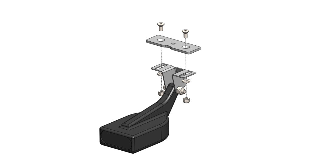
Once the cable is pulled through bolt the transducer and BerleyPro Stainless steel plate together with the m5 countersunk screws in the orientation as shown.
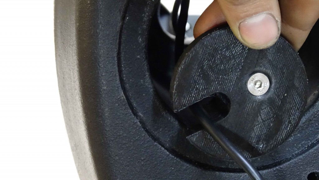
Run the transducer cable through the plastic plug as shown and push it into the round hole at the base of the tackle pod.
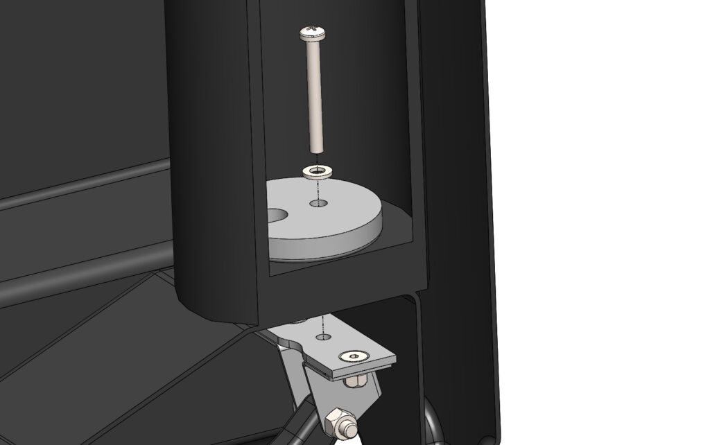
Bolt the stainless bracket to the transducer plug.
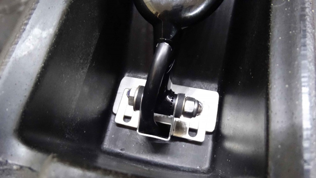
This is how the Lowrance transducer should look when it is completely installed in the base of the Tacklepod.
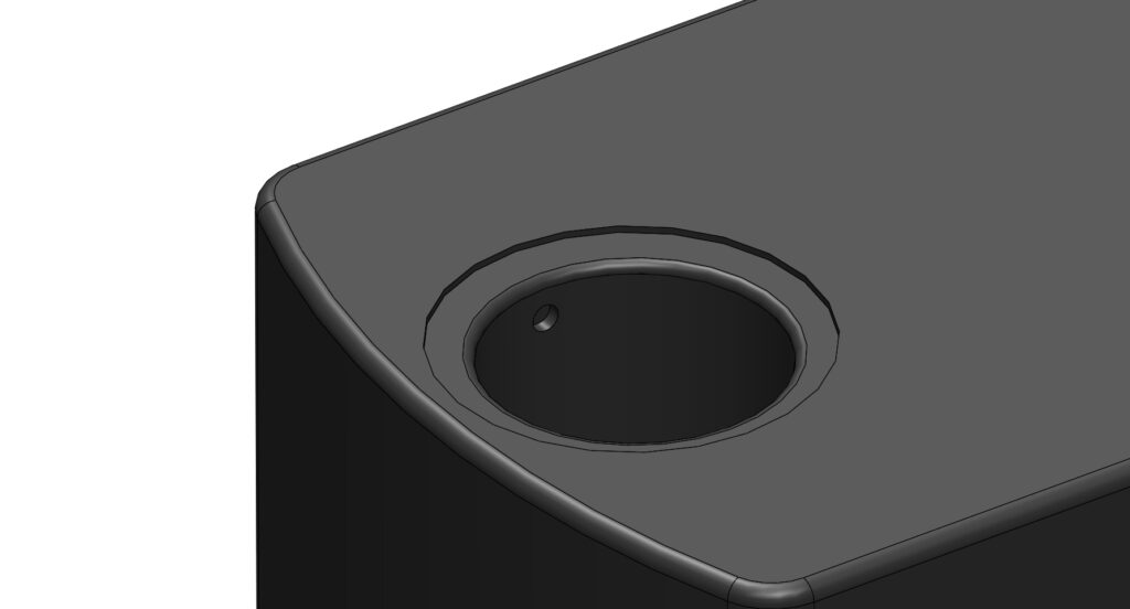
The next step is to drill a hole in the side of the tube as shown to allow the sounder power cable to enter the pod. Make this hole snug on your power cable depending on the diameter of the cable.
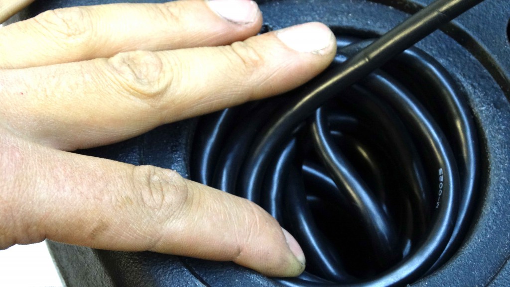
Once drilled then coil the transducer cable up in the recess until you have just enough extruding the hole to allow it to reach the sounder head unit.
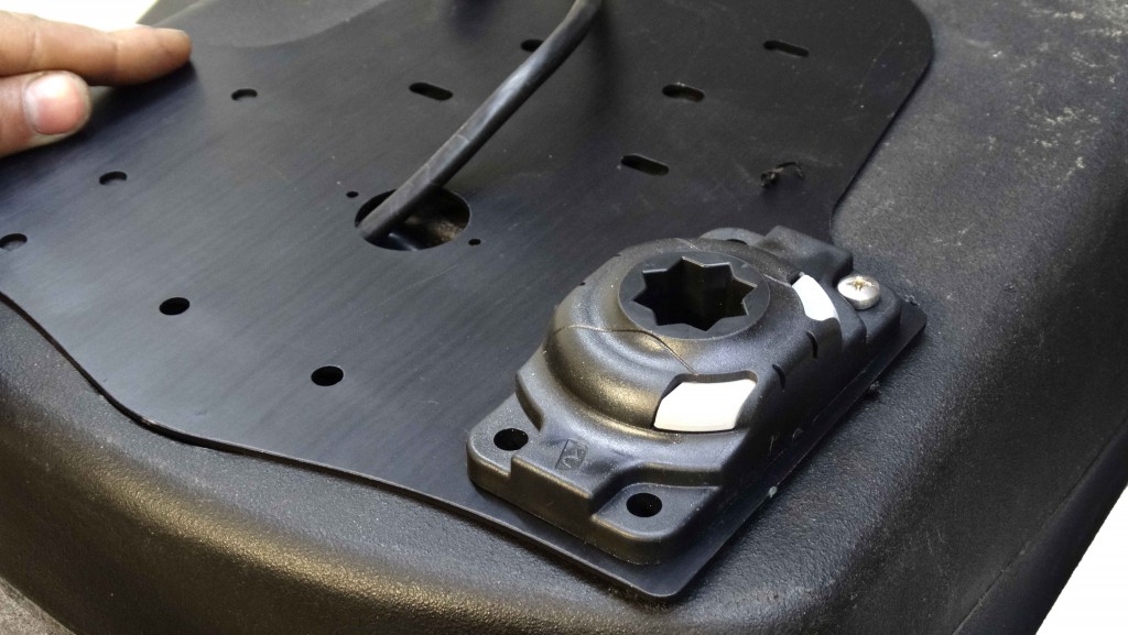
Place the BerleyPro cover plate on the top of the pod. You can line this up flush with radius of the round recess and parallel to the lid flange and then start drilling to suit the mounts you have. It has been drilled to allow either two HD Railblaza starports or 3 normal starports along the front. Click on the attached PDF to see the mount layout.
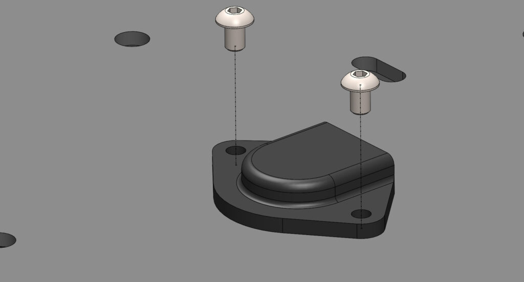
Once this has been done the cable cover can now be installed using the 2 m4 cap screws provided.
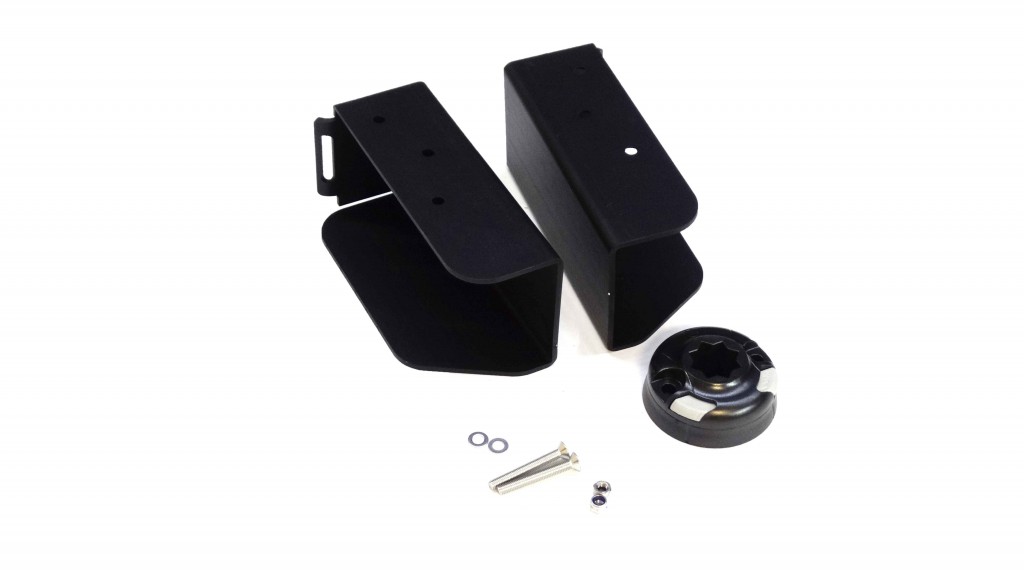
The two battery trays are going to be mounted onto a Railblaza starport in this example with the fasteners provided.
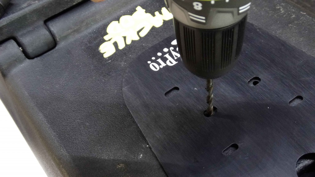
Drill two 5.5mm slots in the center of the two middle slots as shown.
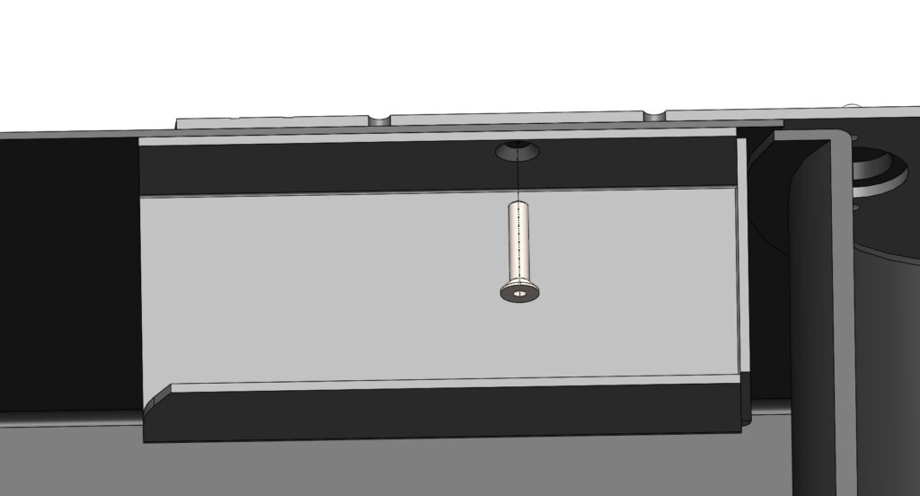
Insert the provided counter sunk cap screws into the battery trays through the Tacklepod.
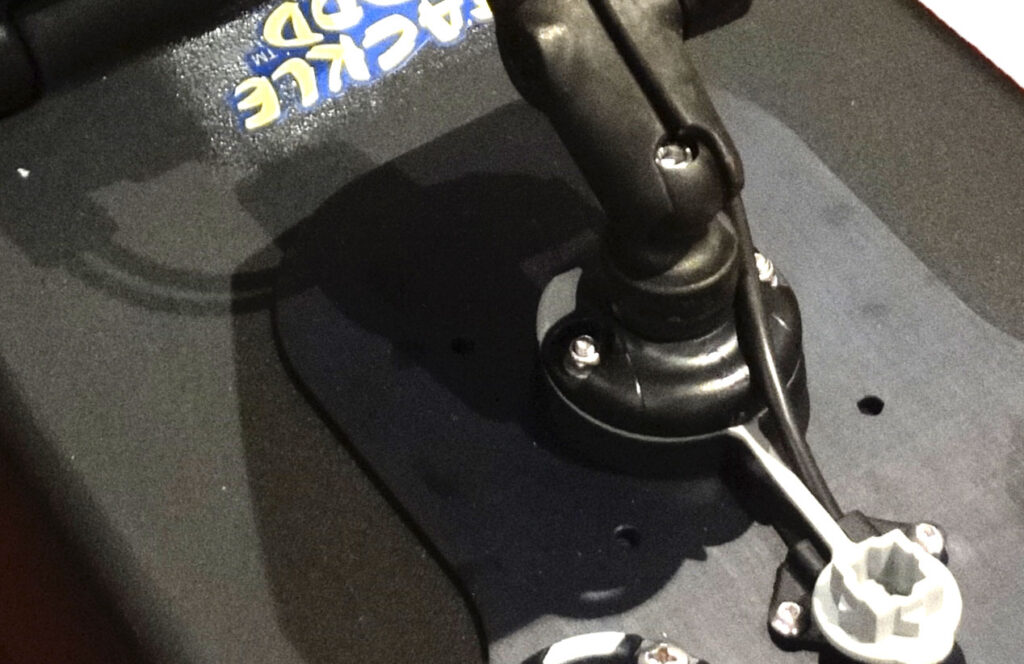
Bolt the a Railblaza Starport and to the top of the cover plate to hold the battery trays up using the two m5 nuts and washers provided.
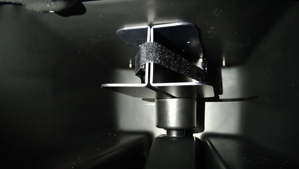
The two battery trays look like this on the inside without batteries in and the Velcro strap installed through the slots on the trays.
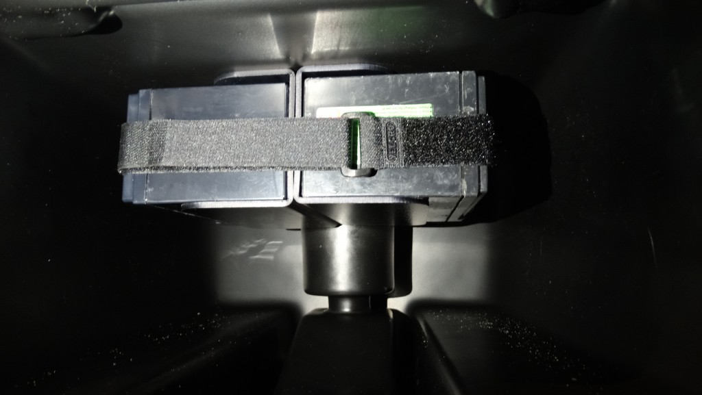
The battery trays can sit two 7 or 9ah batteries in them. This can also be used with only the one battery and they are contained by the Velcro strap around the two batteries.
